


How to Design Animatronic Mechanisms
Good animatronic mechanisms start with a clear understanding of basic mechanical principles. The difference between a figure that moves smoothly and one that binds, stalls, or breaks is almost always decided in the mechanism design phase. This guide covers the core linkages, layout methods, and control approaches used in professional animatronic work.
Start with Basic Mechanisms
It is critical to be familiar with the classic linkages before you design anything complex. In mechanical engineering these relationships are described by kinematics — the study of motion without regard to the forces that cause it.
The most useful building blocks are:
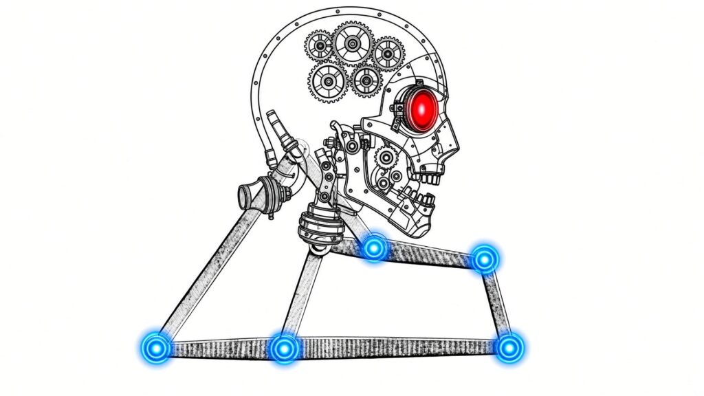
- 3-bar linkages for simple pivoting action
- 4-bar linkages for controlled, predictable paths
- Coupled mechanisms that drive two or more motions from a single input
- Sliding mechanisms that use linear bearings and rail hardware for straight-line travel
These four families cover the majority of animatronic joints, eyelids, mouths, and limbs. Once you can sketch and analyze them on paper or in CAD, more complicated assemblies become straightforward combinations of the same elements.
Lay Out Mechanisms in 2D CAD
Simple designs can be developed as 2D layouts in CAD. Place a fixed mechanical ground (the non-moving base) and leave the pivots unconstrained so you can drag the joints and watch the motion. This immediately shows where a mechanism will lock up, where clearances are too tight, or where the linkage reaches a dead point.
Checking the full range of motion in 2D before you cut metal or print parts saves significant time and material. If the 2D version binds, the 3D version will bind as well.
Match Controls to Mechanism Complexity
Basic controls can be as simple as a motor turning on. Many utility motions (curtain, simple jaw, or continuous eye sweep) need nothing more than power and a limit switch.
Complex controls may rely on inverse kinematics. When a multi-joint arm or neck must reach a specific position in space, the control system solves for the individual joint angles. Professional show-control platforms handle this calculation in real time; simpler hobby controllers generally do not. Choose the control approach that matches the mechanism — do not force a basic on/off motor to perform multi-axis positioning.
FAQ
What are the most useful linkages for animatronics?
3-bar, 4-bar, coupled, and sliding (linear bearing) mechanisms cover most joints and motions.
Why design mechanisms in 2D CAD first?
Unconstrained 2D layouts let you drag the joints and see lock-ups or interference before any parts are made.
When do I need inverse kinematics?
Use inverse kinematics when a multi-joint assembly must place an end effector (hand, head, or eye) at a specific coordinate in space.
Can a simple motor drive a complex mechanism?
Only if the mechanism itself converts that single rotation into the required motion. Otherwise the control system must calculate and command multiple axes.
How can we help you make your animatronic robot? Contact us, we are happy to help!
2026